- B2B Industrial Supplier since 1999
- Shipping from our own warehouse in NL !
- Shipping in EU with DPD Traceable
- Reliable SSL & Secure Payments


Compatibility:
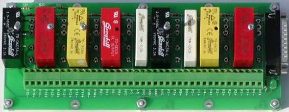
The RB16 biedt a versatile method for electricians, engineers, and other Qualified Individuals, interface to a PC with high voltages / currents. A row of screw terminals Provides the interface to the high level isolated signals. These can be Either 120/240-volt AC signals or 3 to 60 volts DC signals. The DB25 connector biedt the interface to standard logic level signals (+5 volt levels). The RB-16 was designed to be pin compatible with the Labjack U12, All which is a USB-based multifunction data acquisition and control device. The RB16 ook comes with a DB25 male to female cable for connection to the Labjack or other equipment.
I / O modules are available from a variety of manufacturers zoals Grayhill, Crydom, or Kyoto and from distributors zoals Digikey and Future Electronics. The Following are recommended miniature modules:
All modules thesis providence optical isolation between the high voltage side and the logic side. It Should Be Noted That the output modules require inverted logic, that is, a logic low input signal to turn on the output. For an input module, logic sense is normal, that is, if an AC or DC signal is present at the terminal block depending on the type of module, a logic high will be sensed by the Labjack.
The RB16 will accept Either 16 miniature style modules or eight standard-size modules.
The schematic of one section of the RB16 is shown in Figure 1. This circuit is repeated 16 times. An input or output, depending on the module type, comes from a DB25 connector. The output or input is connected to the screw terminals. The screw terminals are Intended To accommodate voltages up to 240 volts AC Either as an output or an input shaft. The DB25 connector signals are low level DC signals.
Resistor R 1 in Figure 1 is a pull-up to VCC (normally +5 volts). Resistor R 2 is a feedthrough resistor for applications where the RB16 will be used as a breakout box for the DB25 signal (s). The application or R2 was Mainly Intended for the Labjack, where the user might want some of the I / O signals brought` out directly to the screw terminals. The resistor can be of any convenient value thatwill pass the signals back and forth. When the user installs this resistor, the module sockets will be blocked from accepting the module.
The Following table shows pin functions out of the DB25 connector.
| DB25 Pin No. | Output Control |
| 1 | R0 |
| 2 | R1 |
| 3 | R2 |
| 4 | R3 |
| 5 | R4 |
| 6 | R5 |
| 7 | R6 |
| 8 | R7 |
| 9 | NC |
| 10 | VCC |
| 11 | VCC |
| 12 | VCC |
| 13 | VCC |
| 14 | GND |
| 15 | GND |
| 16 | GND |
| 17 | GND |
| 18 | R8 |
| 19 | R9 |
| 20 | R10 |
| 21 | R11 |
| 22 | R12 |
| 23 | R13 |
| 24 | R14 |
| 25 | R15 |