- B2B Industrial Supplier since 1999
- Shipping from our own warehouse in NL !
- Shipping in EU with DPD Traceable
- Reliable SSL & Secure Payments


Compatibility :
U3 Series, T7 Series, U6 Series, UE9 Series
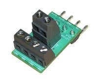
The LJTick-Current Hunt (LJTCS) is a signal conditioning module designed to convert a 4-20 mA current loop input signal into a signal compatible with the 0:47 to 2:36 volt Labjack U3, U6, T7 or UE9. The 4-pin design plugs into the standard AIN / AIN / GND / VS screw terminal block found on newer LabJacks zoals the U3, U6 and UE9. Can not be used with U12. The major advantages of the LJTCS, Compared to using a simple load resistor, are ease of use, high common-mode range, and lower voltage drop on the 4-20 mA signal.
The pins shown on the right side of the LJTCS (Figure 1) connect to the Labjack. The US / GND pin power the LJTCS, while the OUTA / OUTB pin setting the output voltage signal to analog inputs on the Labjack. Following are descriptions of the screw-terminal connections:
SGND: This terminal connects to Labjack ground (GND) with a 750 mA self-resetting thermal fuse in series. Often, the 4-20 mA sensor Has its own power supply, and That supply ground needs to be connected to ground Labjack providence to a common reference. That Allows SGND to be done, but Protects from the risk of the external power supply excess dumping ground current through the Labjack.
VS: This is the same as the 5 volt output terminals on the US Labjack itself. This is an output terminal, not an input. It can be used to providence 5 volt (nominal) power as needed.
INA + / INA (or + INB / INB-): The 4-20 mA current loop shouldering be connected to + INA and INA Such That the current flows into INA + and out of the INA. Each channel HAS A 5.9 Ω measurement resistor, and the voltage across That resistor is amplified by x20. So 4 mA gives about 0472 volts and 20 mA gives about 2:36 volts.
In Addition to the 5.9 Ω shunt resistor, there is a self-resetting thermal fuse in series. This Has A typical resistance of 18 Ω (min = 3.6 and max = 50). This does not affect the measurement, but does affect how much voltage is dropped as the 4-20 mA signal passes through the LJTCS.
The common-mode input range of the LJTCS -8 to +28 volts. That Means That the voltage of each of the inputs must be within range Compared To That LJTCS ground.
If the 4-20 mA signal does not have a common reference at all with the LJTCS, one needs to be made. One common way of doing this is by connecting ground from the sensor to SGND on the LJTCS. SGND Has A fuse in series and then connects to normal GND. The fuse is a 750 mA self-resetting thermal fuse, and Prevents other systems from using the ground as LJTCS Their power ground.
The Following figures show typical connections. Figures 3 and 4 show typical connections with a three-wire sourcing type sensor. This type of sensor sources the 4-20mA signal, then-which is Returned to sensor ground. The common-mode voltage or INA is 0, while the common-mode voltage or INA + is equal to the loading of the signal LJTCS (Typically 0:48 volts @ 20 mA).
| Parameter | Conditions | Minus | Typical | Max | Units | |||
| General | ||||||||
| Supply Voltage | 3.6 | 5 | 12 | volts | ||||
| Supply Current | 0.5 | mA | ||||||
| Operating Temperature | -40 | 85 | ° C | |||||
| Signal Specs | ||||||||
| Gain (1) | 20 | V / V | ||||||
| Sense Resistor (1) | 5.9 | Ω | ||||||
| Gain Accuracy | 0.5 | % | ||||||
| Offset Accuracy | 2 | mV | ||||||
| Total input impedance (2) | 9 | 24 | 56 | Ω | ||||
| Signal Loading (2) | @ 20 mA | 0048 | volts | |||||
| Common-Mode Range (3) | US = 5 Volts | -8 To +28 | volts | |||||
| Typical Output For 4-20mA | 0472 | 2:36 | volts | |||||
| Typical Output Range | 0:02 | USA - 0.2 | volts | |||||
| Typical Input Range | Vout = 0.02 - 4.8 Undesirable volts | 0:17 | 40.7 | mA | ||||
| -3 DB Bandwidth | 1200 | Hz | ||||||
(1) The 4-20 mA signal passes through a sense resistor, and the voltage across That resistor is amplified to produce the output voltage signal. Thus the response of the LJTick-Current is 118 mV / mA.
(2) The total input impedance is the sum of the sense resistor and the thermal fuse resistance, and is Typically 21-27 ohms at room temperature. The voltage dropped across this total impedance by the 4-20 mA signal is the moment.
(3) The voltage from IN + / IN- to GND must stay within the common-mode limits.